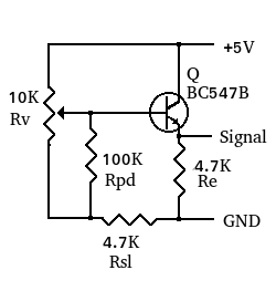
The unit will be used in an e-bike with mid motor and integrated controller. The unit is compatible with hall sensor throttles that use a 3 wire interface (5 volts, Ground and Signal) and can be used with other motor controllers, figure 1 is the schematic of the circuit.
Other materials were purchased from local hardware and Bike stores.
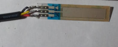
Figure 2 shows a 25mm ThinPot, numbers 1 to 3 identify the pins and letters A and B identify the extreme positions. Pin 3 positive results in maximum throttle in point A while pin 1 positive results in maximum throttle in point B
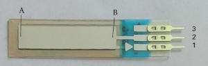
The table below shows the minimum and maximum throttle positions for the two possible connections of the ThinPot.
| Pin 1 | |Pin 2 | |Pin 3 | |Pos. A | |Pos. B |
| +5V | |Signal | |GND | |Min. V | |Max. V |
| GND | |Signal | |+5V | |Max. V | |Min. V |
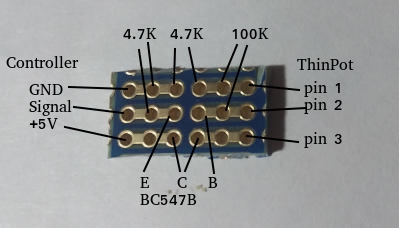
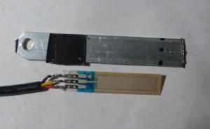
Figure 3 shows the board used with the component location identified. It was cut from a larger protoboard. The right image shows all parts, except the ThinPot, soldered on the board. The 3 conductor cable cable was divided in two, the piece on the right side of the photo connects the ThinPot.
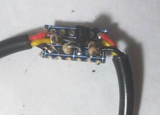
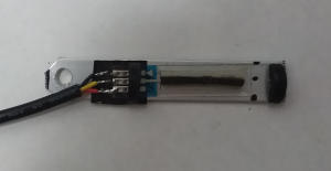
The ThinPot was soldered to the 3 conductor cable using the pin 3 positive configuration. Warning: The ThinPot is heat sensitive and should be soldered using the same precautions as when soldering semiconductors. The wired ThinPot is shown in figure 4.
The assembled circuit was tested at this point of the construction to verify proper functioning.
Handlebar support
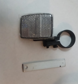
The piece of aluminum bar was drilled at one end to fit the screw of the handlebar reflector. The reflector and its carrier were removed and the screw holding them saved, it will be used to attach the aluminum bar. Figure 5 shows the handlebar reflector, and the drilled aluminum bar.
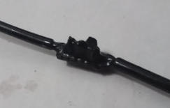
The corners of the aluminum bar next to the mounting hole were cut off to allow it to turn freely when adjusting its position. The Thinpot has exposed crimped connectors that can be shorted if placed over an electrical conductor. A piece of insulating tape was placed over the area where the metal connectors rest to avoid shorting the connectors. Figure 6 shows the bar with the insulating tape next to the Thinpot.
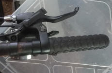
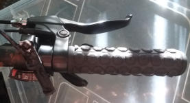
The Thinpot has an adhesive backing, it was used to attach the Thinpot to the aluminum bar. A rubber strip was glued to the center of the active area of the Thinpot, and pieces of rubber were glued about 5mm from each end of the active area. These provide touch feedback while using the throttle. For this unit we used UHU brand plastic cement. Figure 7 shows the rubber strip and end pieces. The piece closest to the soldered end is not clearly visible against the black insulating tape.
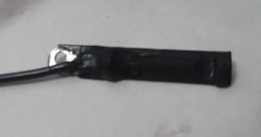
The Throttle end and the circuit board were coated with flexible plastic, we used Plasti-Dip brand. The ThinPot is rated IP64 which is only splash protection, and the solder tabs are exposed. This coating is needed since the high input resistance of the emitter follower can result in activation of the throttle with moisture. In the final step the aluminum bar was attached to the handlebar support. Figure 8. shows the components coated with plastic and the finished Throttle.
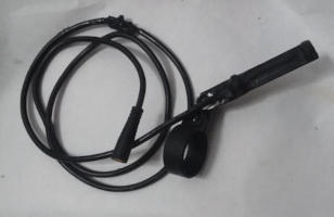
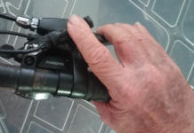
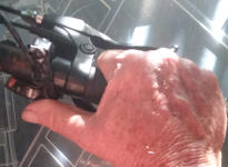
The throttle can be installed for operation with the index finger (Figure 9) or with the thumb (Figure 10).