Vs and GND are the power lines provided by the controller to the throttle.
Signal is the voltage provided by the throttle to the controller, referenced to the ground line.
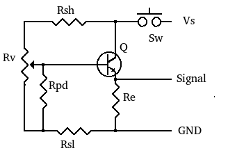
The Spectra Symbol company produces a family of linear position sensors that include force sensitive variable resistors. The resistance of these devices changes when force is applied, for example, by touching with a finger. The throttle design in this document is based on the ThinPot device. A general schematic for the throttle is shown in figure 1.
Vs and GND are the power lines provided by the controller to the throttle.
Signal is the voltage provided by the throttle to the controller, referenced to the ground line.
Rv is the variable resistor(ThinPot).
Q and Re are configured as a common collector amplifier or emitter follower. These should be included if the input resistance of the controller is small. The variable terminal of Rv can be connected directly to controllers that have a large input resistance with a response that will be close to linear. However, for controllers with input resistance close to or below the resistance of Rv the linearity will be poor. The high input resistance of the emitter follower will eliminate this problem and its output can drive both low and high input resistance controllers. Transistor Q can be any npn bipolar junction transistor (BJT) with maximum voltage ratings greater than Vs. The schematic shown is for positive Vs, for negative Vs a pnp BJT is used.
Rsh and Rsl are series resistors that set the voltage range across Rv. Most controllers do not respond to the full voltage range of 0 to Vs, instead responding from a minimum value (Vmin) to a maximum value (Vmax). Rsl and Rsh determine the Vmin and Vmax values respectively that are presented to the controller. If Rsl an Rsh are not needed in an application, at least one of them should be included as a current limiting resistor. Otherwise, if both ends of Rv are touched at the same time it will result in a short that will destroy the conductive traces of Rv. If the circuit requires the use of the emitter follower, the value of Vmin and Vmax should be adjusted to account for the base to emitter voltage drop of the tansistor.
Rpd is a pull down resistor. The variable terminal of the ThinPot floats when not pressed, Rpd is needed to provide a "return to zero" function when the throttle is released. The linearity of the output of Rv is affected by Rpd, its value should be large compared to Rv to minimize this effect. Some e-bike displays expect a non-zero value when the throttle is released. To satisfy this requirement Rpd is connected to the Rv-Rsl node. If the controller or display do not have the requirement, Rpd can be connected to ground.
Sw is a single pole single throw normally open momentary action switch. Sw is a safety cutoff switch that should be included when testing a design. Operation of the throttle requires that Sw be pressed. Releasing Sw, as in case of an accident, will drive the signal to zero.
The circuit schematic for the touch throttle is shown in figure 2.
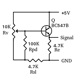
All fixed resistors are 1/4 watt, 5% tolerance.
Rv (10Kohms) is the variable resistor (ThinPot).
Rpd (100Kohms) is the pull down resistor.
Rsl(4.7Kohms) is used to set Vmin to about 1.6 volts. We selected this value to offset the base to emitter voltage drop of about 0.7 volts of the transistor. This value is the closest E12 standard resistor value to get Vmin, the next E12 value of 5.6Kohms results in Vmin too close to 1.1V. The resulting value of Vmin at the emitter of Q1 will be about 0.9 volts. For Vmax the value is about 4.3 volts so Rsh is not required.
Q is a BC547B npn bipolar junction transistor.
Re(4.7Kohms) was selected to limit the number of different components. The no load current required by the throttle will be below 2 milliamperes.
We have tested the above circuit with several e-bikes. A mid motor integrated controller and color display, a throttle only 500 Watt brushed motor controller without a display, and a 1500 Watt controller used with a brushless hub motor and a monochrome LCD display.In all tests the e-bikes performed in a normal fashion.